Vector PDF to DXF converter
Drop a PDF exported from CAD, Illustrator or a plotter driver below. Its lines, curves, filled shapes and text come out as a DXF R12 file with one layer per colour, at true size once you set the scale.
Updated 2 November 2026
Drop a PDF here or click to choose one
Converted on your device. Nothing is uploaded. Several PDFs at once with the batch pass.
PDFs to convert (every page of each, at paper size, one DXF per PDF in a ZIP):
This vector PDF to DXF converter reads the drawing instructions stored inside a PDF, the lines, curves, filled shapes and text that a CAD program, Illustrator or a plotter driver wrote into it, and writes each one back out as a DXF entity you can select and edit. Nothing gets traced or guessed, so a 40 m site boundary comes back as 40 m, to a hundredth of a millimetre. The conversion runs in your browser and the drawing never leaves your computer.
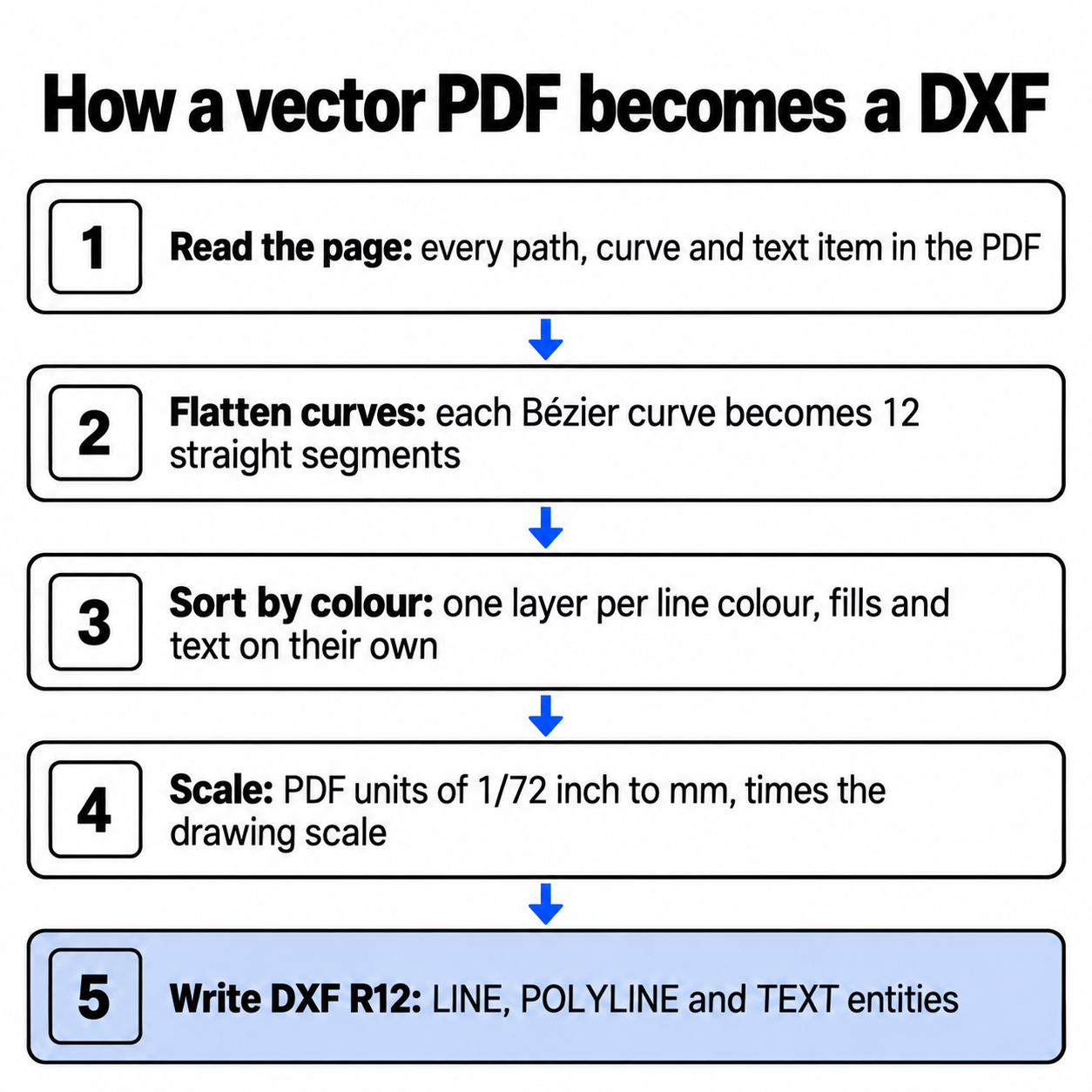
What counts as a vector PDF?
A PDF stores a page in one of two ways. A vector PDF holds instructions such as “line from here to there, 0.35 mm, red” and “text OAK LANE, 9 pt, rotated 90 degrees”. A raster PDF holds a picture of the page, made of pixels.
You get a vector PDF when the drawing is exported from software: Plot to PDF in AutoCAD, a sheet export from Revit or ArchiCAD, SketchUp LayOut, Illustrator, Inkscape, or a print to PDF straight from a CAD program. You get a raster PDF from a scanner, a phone photo or a JPG saved as PDF. The test takes ten seconds: zoom to 800 % on a corner. Sharp edges mean vector. Blurry steps mean pixels, and the scanned PDF to CAD page covers that case.
What does the converter do with each part of the drawing?
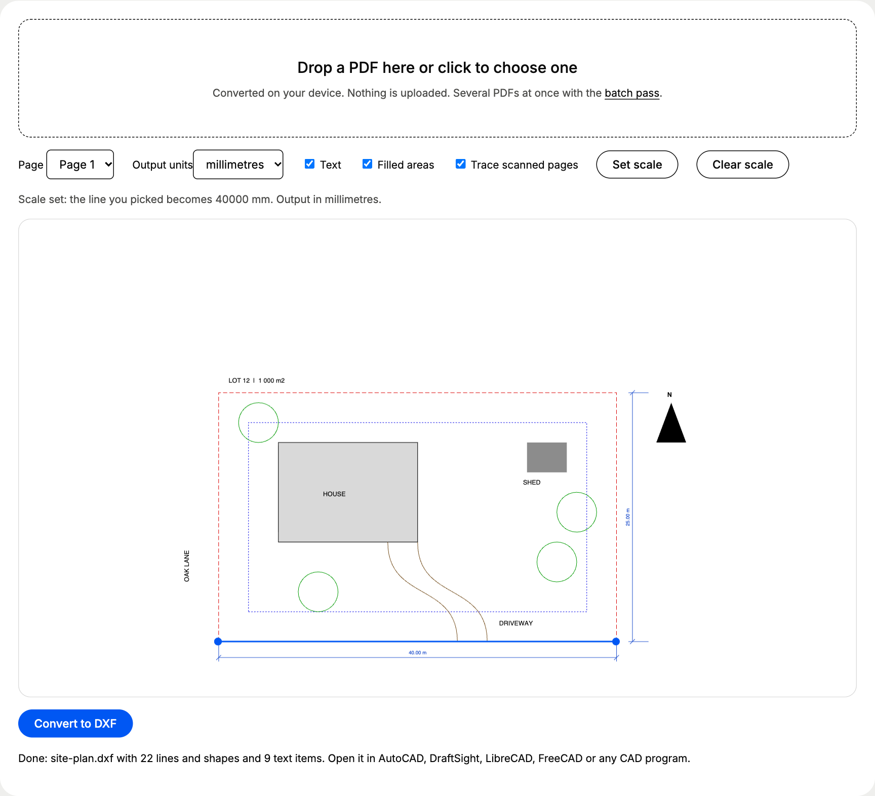
To check every kind of vector content in one file, we drew a test site plan of a 40 x 25 m lot at 1:200 on A3. It has a dashed red boundary, a dashed blue setback line, a house drawn as a grey fill with a black outline, a shed drawn as a fill with no outline, a curved driveway made of Bézier curves, four trees, a filled north arrow and a street name rotated 90 degrees. Here is what came out of the converter:
| Element in the test PDF | How the PDF draws it | What the DXF R12 holds |
|---|---|---|
| Lot boundary, red dashed | Stroked path with a dash pattern | 1 closed POLYLINE, solid, layer PDF_D90000 |
| Setback line, blue dashed | Stroked path with a dash pattern | 1 closed POLYLINE, solid, layer PDF_0000E6 |
| House | One path, filled grey and stroked black | 1 closed POLYLINE outline on PDF_000000; the grey fill is dropped |
| Shed | Grey fill with no outline | 1 closed POLYLINE on PDF_FILL_8C8C8C |
| North arrow | Black filled triangle | 1 closed POLYLINE on PDF_FILL_000000 |
| Driveway | 2 Bézier curves | 2 POLYLINEs, 12 segments each, layer PDF_734C1A |
| Trees | 4 circles | 4 closed POLYLINEs, 48 segments each, layer PDF_009900 |
| Dimensions | Short lines and tick marks | 10 LINEs on PDF_1A4CCC |
| Labels, street name, title | Text items, one rotated 90 degrees | 9 TEXT entities on PDF_TEXT, OAK LANE still at 90 degrees |
That is 22 lines and shapes plus 9 text items on 9 layers, with 241 polyline points in all. Every colour in the PDF became its own layer, which is the quickest way to sort a drawing you did not make: freeze PDF_1A4CCC and the dimensions disappear, freeze PDF_TEXT and only geometry is left.
What does the converted site plan look like?
We loaded the site plan into the converter on this page, clicked Set scale, picked both ends of the 40.00 m boundary and typed 40000 mm. The blue line shows the picked distance.
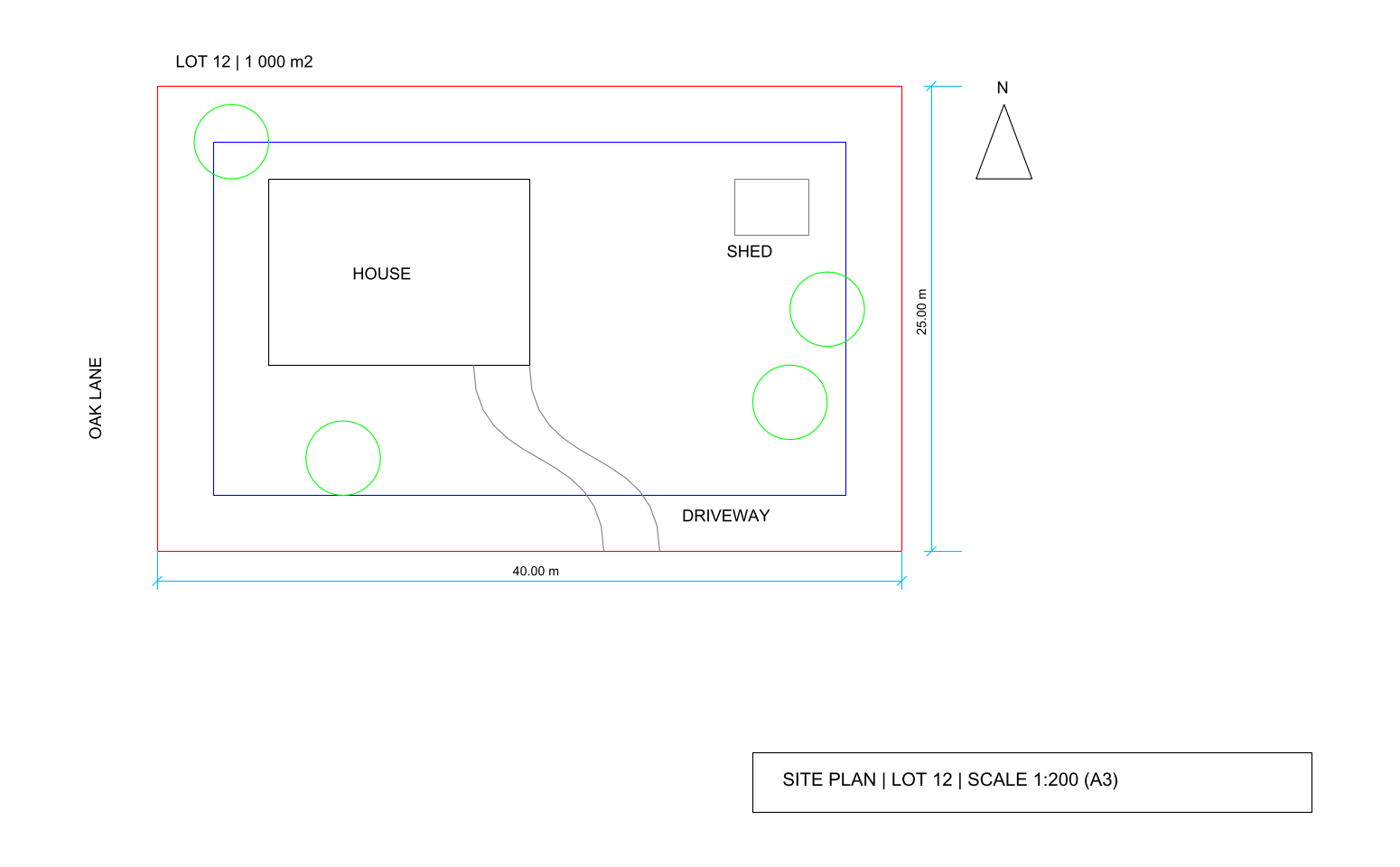
Download both and open them in your own CAD program: site-plan.pdf and site-plan.dxf. The DXF here was made with the 1:200 factor typed in, so the boundary measures exactly 40 m.
How accurate is a vector conversion?
We measured both DXF files with ezdxf, the open-source Python library for DXF:
The two-click scale lands at 0.036 %, the same share we measured on the 10 m wall of our floor plan test. The click picks a screen pixel, so the longer the line you pick, the smaller the error in millimetres. The gap between a vector PDF and a scan is far larger:
Error on the 10 m wall of the test floor plan
| Vector PDF | 1 µm |
|---|---|
| Vector PDF | 3,600 µm |
| Scanned PDF | 38,000 µm |
All five benchmark drawings and their files are on the accuracy results page.
Which settings matter for a vector PDF?
| Setting | What to choose | Why |
|---|---|---|
| Output units | Millimetres for metric drawings, inches for imperial ones | DXF R12 stores numbers without a unit, so your CAD program reads them in whatever unit it expects |
| Set scale | The longest dimensioned line you can find | A 1:200 drawing is 200 times too small on paper; a long reference keeps the click error small |
| Text | On | Labels, dimension figures and title blocks stay editable TEXT |
| Filled areas | On for solid arrows, hatch blocks and fill-only shapes | Off drops every shape that has a fill and no outline, such as the shed and the north arrow |
| Trace scanned pages | On | It only acts on pages that turn out to be scans, so a mixed set converts in one go |
What does a vector conversion leave out?
Six things change on the way, and none of them moves a line:
- Line styles. Dashes, dots and line widths arrive as solid CONTINUOUS lines.
- Curves. Each Bézier curve becomes 12 straight segments. For CAM programs that need true arcs, the PDF to DXF R12 converter page shows how to rebuild holes as circles.
- Fill colour of outlined shapes. A shape drawn as fill plus outline keeps its outline only, like the house.
- Images. Photos, raster logos and aerial backgrounds stay behind.
- Clipping. A CAD program that crops a viewport with a clipping path still writes the hidden lines into the PDF, and they come across into the DXF. Delete them in CAD.
- Fonts. Text keeps its content, height, position and angle, and takes the STANDARD text style of your CAD program.
For the full picture, including scaled drawings, scans and which programs open the result, start at the PDF to DXF converter page.
Questions about vector pdf to dxf converter
How do I know my PDF is a vector PDF?
Zoom to 800 % on a line or a letter. A vector PDF stays sharp at any zoom, and in most PDF viewers you can select its text with the mouse. A scan turns into blurry, stepped pixels. The converter checks this as well: a page with images and almost no paths or text is treated as a scan and traced.
Does the converter keep dashed lines and line weights?
It keeps the geometry and drops the line style. Dashed lines arrive solid with the CONTINUOUS linetype, and line widths are left behind. Each colour already sits on its own layer, so giving a layer the right linetype and lineweight in your CAD program takes one click per layer.
Are curves and circles written as arcs?
They are written as polylines. Every Bézier curve in the PDF becomes 12 straight segments, so a full circle has 48. On the 4 m tree crowns of our test site plan the segments stay within 4.8 mm of a true circle, about 0.12 % of the diameter.
What happens to photos and logos inside a vector PDF?
They are left out. The converter reads paths and text, so a photo, a pasted raster logo or an aerial image under a site plan does not appear in the DXF. Everything drawn as lines, shapes and text around it comes across.